
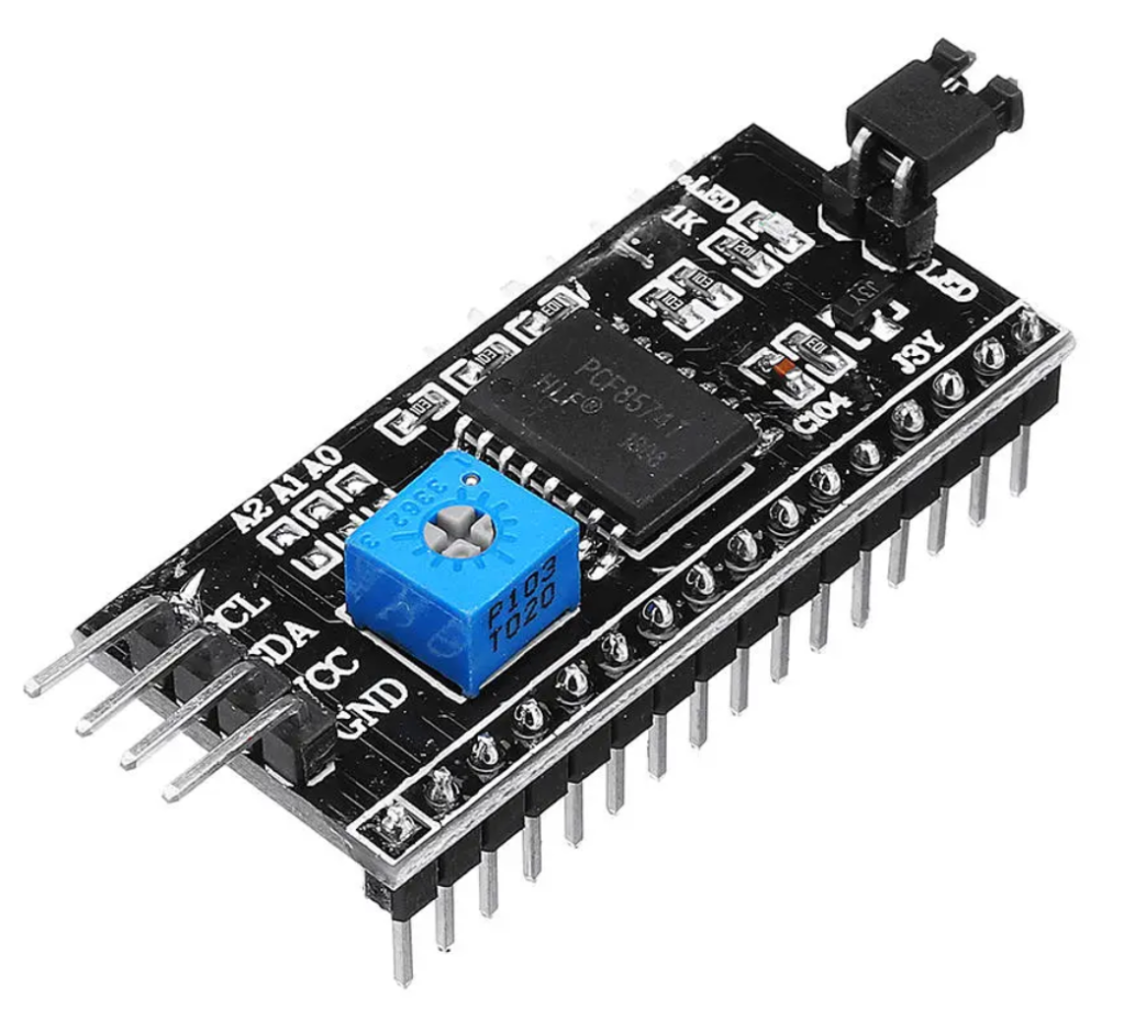
Preparing the LCD Module
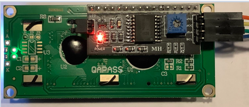
Solder the I2C module on the back of the LCD display.
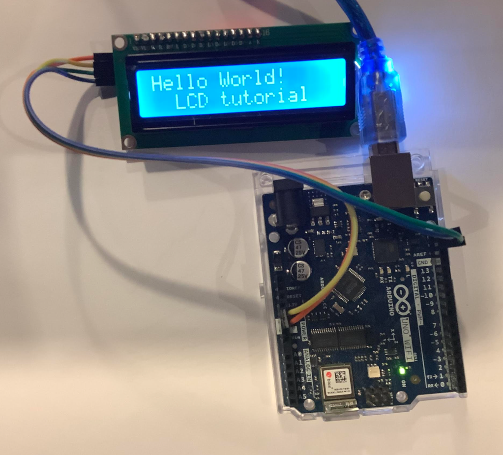
Connecting the Display to the Arduino Wifi Board
Connect 5V, GND, SCL and SDA to corresponding markings on the Arduino board (see image above).
Programming the Board
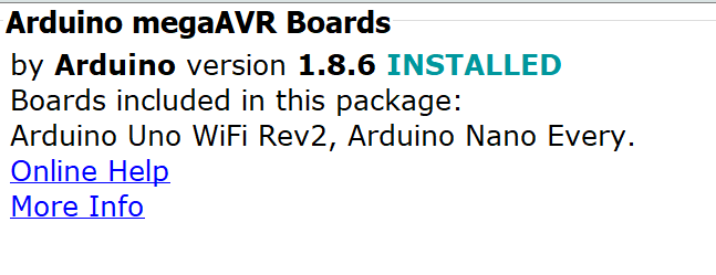
In the Arduino IDE, go to Board Manager and install:
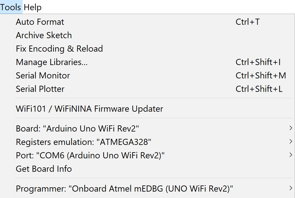
Now select the following (your COM port may differ):
Sketch
Note: to find the address of the device , first run I2C Scanner Code.
For my LCD display it defaulted to 0x27
/* I2C LCD with Arduino example code. More info: https://www.makerguides.com */

// Include the libraries:
// LiquidCrystal_I2C.h: https://github.com/johnrickman/LiquidCrystal_I2C
#include <Wire.h> // Library for I2C communication
#include <LiquidCrystal_I2C.h> // Library for LCD

// Wiring: SDA pin is connected to A4 and SCL pin to A5.
// Connect to LCD via I2C, default address 0x27 (A0-A2 not jumpered)
LiquidCrystal_I2C lcd = LiquidCrystal_I2C(0x27, 16, 2); // Change to (0x27,16,2) for 16x2 LCD.

void setup() {
  // Initiate the LCD:
  lcd.init();
  lcd.backlight();
}

void loop() {
  // Print 'Hello World!' on the first line of the LCD:
  lcd.setCursor(0, 0); // Set the cursor on the first column and first row.
  lcd.print("Hello World!"); // Print the string "Hello World!"
  lcd.setCursor(2, 1); //Set the cursor on the third column and the second row (counting starts at 0!).
  lcd.print("LCD tutorial");
}
That completes the post.
Next, I will get the WIFI going to display the Bitcoin price ticker on the LCD.

One thought on “Using an Arduino Wi-Fi Board Rev 2 with a 16×2 LCD 1602A with I2C module”